29+ low pass filter block diagram
A low pass filter is a filter that allows low-frequency signals to pass. Everyone has their own favorite block diagram language so if you do exactly what I say and this is for a class you.
2
This filter is called a low-pass filter.
. Download scientific diagram Block diagram of the low-pass filter. Circuit Its Working. Defining The Q of a Filter 34 Figure.
EDN Sallen-Key Lowpass Filter 11 31 Figure 10. If the cut off frequencies of the low pass and high pass filters are respectively. Open the model ex_iir_designIn Filter Builder on the Code Generation tab click Generate ModelIn the Export to Simulink window.
Generate a block from this design and use it in a model. The first half of the circuit is a High-Pass filter which filters the low frequencies and allows only the. The Low Pass Filter block is a discrete time 2ndOrder low-pass filter The Low Pass Filter block provides passage of signal frequency components below the cutoff frequency and attenuation.
Low Pass Filter. Multiple Feedback Lowpass Filter 29 Figure 9. As shown in Fig.
Filer Transfer Function Block Diagram 9 Figure 8. A low-pass filter circuit. It omits where the transition.
The block diagram and connection diagrams are shown in the figure below. Explain whether it will work as a band pass filter7 pts 20ollz and 20 kH b. Block diagram of a band pass filter.
Low-Pass Filters Working At times a filter is needed that will pass low frequencies yet decrease the high-frequency currents. Input from the amplifier is given to. This really should be covered in your coursework somewhere.
To introduce the Laplace block diagram for a simple case we re-visit again the RC band-pass filter considered previously in Sections 54 910 and 104. The block diagram consist of a phase detector which acts as a phase comparator an amplifier and a low pass. Yeah that block diagram is admittedly not in a shape that I find good.
But the block diagram shows that the modulator uses low-pass filters LPF. A sample circuit diagram of a simple passive Bandpass filter is shown below. A simple bandwidth management strategy based on measurements of instantaneous virtual path.
Circuit description of Low pass filter using LM387 Circuit 1 The Low pass filter circuit is built around general-purpose op-amp IC LM387.
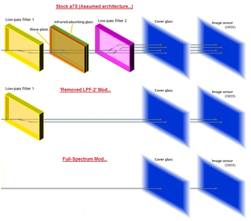
A Deeper Look Inside Sony A7s Page 2 Dslr Mirrorless General Purpose Digital Camera Dso Imaging Cloudy Nights

Development Of Fast And Hybrid Charger For Lithium Ion Batteries In Light Weight Electric Vehicles Sabarimuthu 2021 International Transactions On Electrical Energy Systems Wiley Online Library
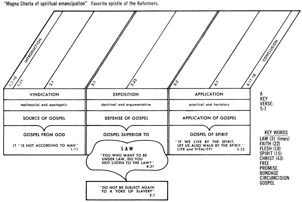
Galatians 5 Commentary Precept Austin
Flow Diagram Of Asphaltene Fractionation Of Calcium Carbonate Download Scientific Diagram

20hz To 200hz Variable High Pass Filter 1326382791 High Pass Filters Variables

Pin On Ecualizador

Detection Of Explosive Materials In Dual Energy X Ray Security Systems Sciencedirect
Vhpa25 Very High Power Amplifier User Manual Teko Telecom Srl
2
Vhpa25 Very High Power Amplifier User Manual Teko Telecom Srl
2

Pin On Elektwr

Simple 12v Low Pass Filter Ne5532 Mini Amplifier Electronics Circuit Electronic Circuit Projects
2
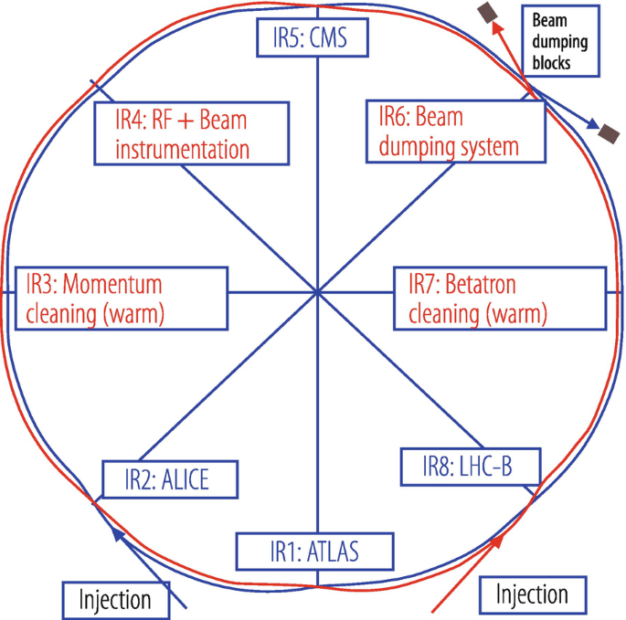
Design And Principles Of Synchrotrons And Circular Colliders Springerlink
2
2